

Back when it was worth trying to fix floppy drives they provided this diagram and gave the proper resistance for each coil and how they should look when you were probing each section. I went ahead and labeled these since you'll have to figure out what part is which on your own.
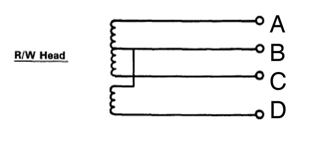
A couple of useful observations: The resistance between A and C should be the same as the resistance between A->B and B->C added together. or:
A->C = (A->B) + (B->C)
also:
A->D = (A->B) + (B->D)
and:
C->D = (C->B) + (B->D)
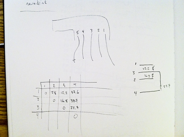
I made a little chart for each head I was working on and then labeled each connection so that I would know what it should look like. It doesn't have to be pretty, this is how mine looked: